Model-driven development of CANopen components
Author: Ansgar Meroth - Heilbronn University - Max-Planck-Str. 39 - D-74081 Heilbronn
Introduction
CANopen for Lifts, specified in CiA 417, has reached a maturity that allows fast development cycles, short integration times and easy maintenance. This article shows the usage of model based development methods and hardware-in-the-loop (HIL) testing for lifts, following well-known schemes from automotive engineering and transforming them for lifts. This work is based upon the modeling of a lift system by Matlab/Simulink, which later will be used as a HIL test bench. The paper discusses how conformity tests and integration tests can be conducted in the proposed environment. Furthermore a demonstrator lift is presented that takes advantage of the proposed ideas.
The histories of elevators and vehicles share several noteworthy commonalities.Cars started at the end of the 19th and the beginning of the 20th century as mechanical systems with electromechanical components – mainly ignition. Steam-driven lifts started to be employed in 1850, and were driven by electrical engines by 1880. In the 1970s,electronic components entered both worlds, first replacing single electromechanical parts, and in the 1990s, networking started to spread out so that complex and expensive wiring could be replaced. The next development step, however – model-driven development and automated integration and testing is rather further developed in the automotive industry, driven by cost and safety requirements.
Integration of lift components
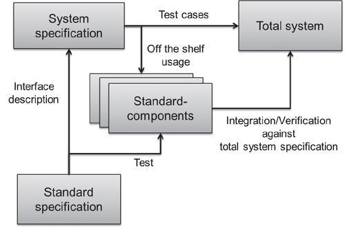
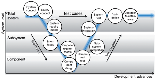
In 2002, CiA 417 for lift control systems was specified in order to interconnect lift components with a common open interface. Many virtual devices have been created that add up to a complete lift system, such as an input panel unit, an output panel unit, a call controller, a car door unit, a car door controller, a light barrier unit, a car drive unit, a car drive controller, a car position unit, a load measuring unit, and a sensor unit. As a consequence, system specifications, system integration and maintenance can be performed by independent suppliers (Hellmich & Prof. Dr.-Ing. Ansgar Meroth others). The common open interface helps reduce development life cycles and time to market, especially in light of the challenging requirements of IEC 61508, the basic functional safety standard (International Electrotechnical Commission (IEC), 1998). These requirements have implications on the developing process, which challenge the integration of lift components in several ways. (Gutmann, 2010). The development of safety critical systems usually follows the V-model as shown in Figure 1. This approach would theoretically require a long development time since all the specifications are made with a top-down-approach, in which the test cases for integration and verification are also elaborated. Consequently,system integration and verification is performed in a bottom-up-process. Using well known common interface specifications on subsystem and component level can reduce the development efforts considerably by taking advantage of offthe- shelf components and a parallel integration process on the subsystem level as shown in Figure 2.
Each new component can be tested against the CiA 417 specification and integrated into a system that follows the standard and uses CANopen messages as interface. There is, however, a practical drawback, which is the fact that lifts need to be highly customized and individual. In other words, integrating and testing a new component would require the presence of the entire remaining lift system.
Hardware in the loop
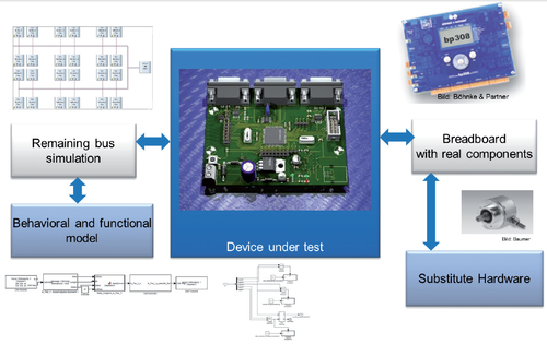
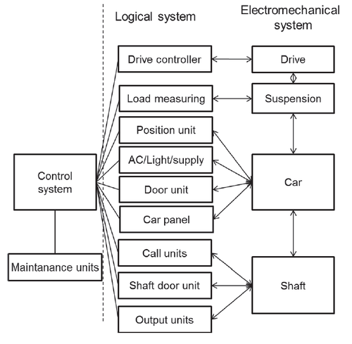
The problem is well known and well solved in the automotive industry (Schäuffele & Zurawka, 2010). From the beginning of their functional specification, new components undergo a test and integration process against a simulated total system. The future system is specified by taking advantage of a modeling tool chain, obeying a system architecture previously agreed on, and relying on CANopen messages as interface. Figure 3 shows a corresponding architecture,which is implicitly derived from CiA 417. We propose a modeling tool chain that includes:
- A mechanical model of the system that takes weight and load parameters of the car into account, including a suspension model with – in case of a rope – appropriate tension and friction parameters as well as location, speed
and acceleration,
- An electromechanical model that converts resulting load, speed and acceleration into drive engine load, torque and
rotation and furthermore into electrical load,
- A logical model that calculates the user requests into drive parameters,which is what the lift control does. The logical model also represents the information flow in terms of CANopen messages.
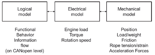
Figure 4 shows some of the main parameters that have to be processed by the different models, which are connected by CANopenlike data structures. Step by step, the system model can be replaced by real components using a real time prototyping system that is directly programmed with Matlab/Simulink generated code as shown in Figure 5.A test bench realized this way consists of the real or simulated device under test (DUT), a so-called breadboard with real components (sometimes supported by substitute hardware that simulates sensor input), a behavioral and functional model of the total system,and the remaining network traffic. In order to supervise the CAN network and to simulate remaining logical behavior, e.g. calls, CANoe by Vector can be used in addition to Matlab/Simulink.
Test System
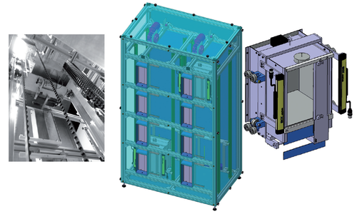
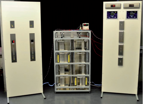
For the demonstration of the development life cycle stated above, we developed a 1:10 scale lift model as shown in Figure 6. This model was originally inspired by Jörg Hellmich, formerly at Böhnke + Partner and now CEO of ELFIN GmbH. We used an aluminum frame made from industrial profiles for the two shafts and placed two cars on steel ropes with a counter weight and driven by DC motors commutated with electromechanical contactors. We hope to receive an asynchronous drive with an inverter from the lift industry in the future.
The system is controlled by two bp308 controllers from Böhnke + Partner and takes advantage of original components, e.g. call units, light barriers, outputs, car electronics, position sensors and others. Even the safety circuit is constructed as close to an original system as possible. At the moment we are developing a virtual model of the components in order to replace the virtual and the real parts. For that reason, we have started to implement a simulation of CANopen messages of the system by means of Vector’s CANoe and a behavioral model with Matlab/ Simulink. Figure 7 gives impressions of some components of the real model. The final goal is to have a test system ready that can be used for static and dynamic conformity tests and allows a reduced integration and verification life cycle with single components.
Bibliography
- Gutmann, K. H.(2010). Funktionale Sicherheit (SIL) in der Anlagensicherung. Lecture at the HS Augsburg in the context of the VL Prozessleittechnik.
- Hellmich, J. & others. Referenzaufzug für CANopen Lift. Accessed January 31st, 2013 at http://www.canopen-lift.org/wiki/Referenzaufzug.
- International Electrotechnical Commission (IEC). (1998). IEC 61508-0. Functional safety of electrical/electronic/programmable electronic safety-related systems.
- Lang, S., Melzer, M. & Brandner, R. (2013). Inbetriebnahme und Optimierung einer Modellaufzugsanlage mit offenen Schnittstellen. Heilbronn: Hochschule Heilbronn - Masterprojekt.
- Meroth,A. & others.(März 2012).Komponentenintegration im Modellmaßstab. Lift Journal.
- Schäuffele, J. & Zurawka, T. (2010). Automotive Software Engineering.4th edition. Wiesbaden:Vieweg und Teubner.
- SIG CANopen Lift. CANopen-Lift. Accessed July 14th, 2013 at http://canopen-lift.de.
