Value adding by linking of CANopen CiA 417 components in the lift
Quelle: CAN Newsletter. Hendrik Bär, Böhnke & Partner GmbH


In the CANopen application profile for lifts (CiA 417), the most essential devices with CAN bus connection for entire lift group are described. This has the advantage that the communication among units is standardized. Devices behave in the same manner, independent of the manufacturer. This can be illustrated particularly in the example of the load measuring device and its connection to the lift controller bp308 (Figure 1), of Böhnke + Partner GmbH.
The overload signal is mandatory for each lift. This sends to the lift controller the signal for an overloaded car and the lift doesn’t work. A simple contact with regulating screw can be used for this implementation. For a better transport efficiency, particularly in the case of lift groups, the lift controller requires the signal of full load, for example when the car is loaded to 80 %. For misuse detection or different special functions, the minimum load signal that reports an empty car is helpful.
A conventional load meter sends the signals of full load and overload. Threshold values can be set on either in the device by a potentiometer, or in the menu. These devices can optionally send additional signals in the form of relay contacts, which must be wired to the lift controller. The lift controller requires appropriate inputs for it.
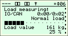
A load measuring device with the CANopen lift interface provides additional discrete signals, such as reduced load, slack rope, rope difference. Furthermore, it informs the effective car load in kilograms (Figure 2). All this information is transmitted via the CAN-bus line, which consists of only two wires.
The information sent by the load measuring device on the CAN bus is available to all devices connected to this bus. This way the frequency converter (drive unit) can also use the effective car load to optimize the start-up behavior and prevent unwanted turning away (undesirable car movement in the opposite direction) at the start.
The lift controller bp308 transmits the effective car load also to the monitoring system WinMOS300® (software package for remote monitoring of lifts). In the case of a continuous connection to the lift system, WinMOS300® can store these values cyclically in a database and provide subsequent statistical analysis. In the application profile for lifts the parameters of the load measuring device are defined. The device can be adjusted this way by the lift controller with the control displays (Figure 3). This is of particular advantage especially when the load measuring device is inaccessible. The individual thresholds for reduced, full and overload can be modified and stored in the lift controller. If the substitution of the load measuring device becomes necessary, the values can be written in the new device. The zero-point calibration of the load meter (tare function), can also be done by the lift controller (Figure 4).
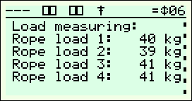
If the load measuring device has a sensor at each track rope, the individual rope loads can also be displayed on the control display. This display can be used to balance the tension of the ropes, since the difference between the ropes must not be too large (Figure 5).
All these added values can be generated with a reasonable effort, since the components used are not wired together in a conventional way, but they communicate via the CAN bus to the application profile CiA 417.